Music-Visualizing DMX Controller
Chris Dzombak, Mike Metzger
EECS373 Spring 2011
Introduction
Our final project for EECS373 is a stage lighting controller that can be used at concerts, clubs, etc. to quickly and easily create a light show synchronized to music. It takes a line-level audio input (from a mixer or iPod) and controls sets of stage lights in realtime based on the bass, midrange, and treble content in the music. (A simple way to think of this is as a 3-band graphic equalizer which outputs lighting control signals instead of having a dedicated visual display.) The project also takes a lighting control input from an upstream lighting control board and passes those control signals to the stage lights along with its own music-controlled signals.
The system can be the primary lighting controller in a club, or it can be used to supplement the primary lighting control system in a concert or a (musical) theatrical production. It can be programmed in realtime - that is, the user can add or remove DMX dimmer addresses from each frequency band while the show is running. The product could be marketed to small music venues (like Ann Arbor's Blind Pig), clubs, concert lighting companies, and theatrical production companies and lighting designers.
If you want, you can click here to skip ahead to the results and videos.
DMX512
Some simple background information on this protocol will be useful in reading this document.
The system operates on the DMX512 lighting control protocol, an older, simple protocol atop RS-485. Each DMX-controlled light is assigned an address from 1 to 512. DMX sends an 8-bit value, 0-255, to each light. A group of 512 or fewer DMX-controlled lighting instruments is called a "universe". For additional information about DMX, see the Wikipedia page.
Design
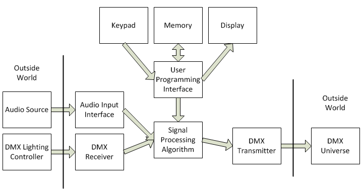
High-Level Overview
Our design is fairly simple. An audio stream comes into the processor from an external input. The audio is divided into frequency bands, and the DSP algorithm (described in detail below) uses peak detection and a running average of the input volume level to continuously assign a DMX output value to each band.
These DMX values are then merged with the DMX input signal from an upstream lighting control board (if present) and transmitted to the DMX universe.
Digital Hardware
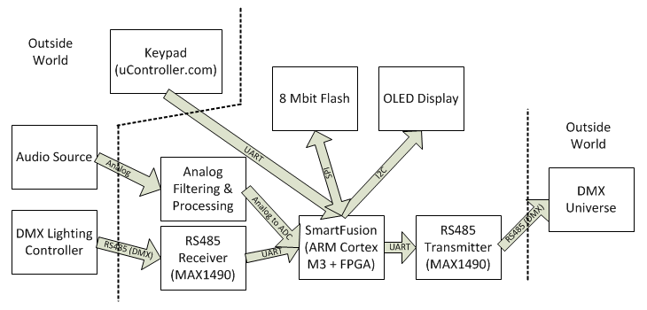
The design was implemented on a Microsemi SmartFusion evaluation board. The SmartFusion platform integrates an ARM Cortex-M3 hard core and a Microsemi FPGA on the same chip. Our design uses several blocks of dedicated digital hardware on the SmartFusion's FPGA as well as several components built onto the SmartFusion eval board.
DMX Transmitter & Receiver
Our design uses the Verilog DMX TX/RX cores from the open-source Milkymist SoC to handle the DMX interfaces. These cores implement the complete DMX512 protocol in hardware; they let us read and write DMX values simply by reading and writing configuration registers.
This implementation was extremely beneficial; if we had implemented DMX in software using a hardware UART, the interrupt traffic (for transmitting and receiving simultaneously) would have cost a significant amount of processor time, which is better spent on DSP.
The Verilog source for these cores is available from the Milkymist project on Github.
APB3-CSR Bridge
The DMX cores use a simple bus called the CSR bus. We needed to talk to them using the ARM's APB3 bus, so we wrote a Verilog bridge module to be used between an APB3 master and a CSR slave.
This was complicated by the fact that the cores required 13 bits of address space, but with the SmartFusion MSS (see below) on the FPGA, we couldn't dedicate that much address space for the DMX cores. To solve this problem, we wrote the bridge such that it includes both an address and data register; first the target CSR address is written into the address register, then data can be read or written to the CSR bus via reads/writes to the bridge's data register.
We released the bridge as open-source hardware; the Verilog source is available on Github.
RS-485 Transceiver
For the DMX interface, we used a single Maxim MAX1490 transceiver. This provided an easy-to-use isolated, ESD-protected RS485 transceiver. It is an expensive (and physically large) part, but we decided that these costs were outweighed by the built-in simple isolation and protection.
Keypad and UART
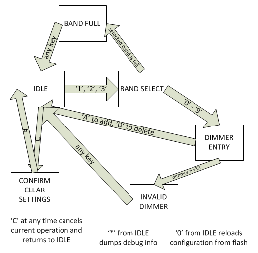
The system is programmed using a numeric keypad. (Additionally, the asterisk key on the keypad dumps debug data from the device to a USB RS232 interface on the eval board.) The keypad, from uController.com, has a simple UART interface.
We used a UART peripheral on the FPGA to interface with the keypad. We chose Microsemi's CoreUART to minimize implementation time.
SPI Flash
We used the 8 MByte SPI flash on the SmartFusion eval board to store the user's settings. The settings are written into flash whenever the user changed them, and they are read out from flash on boot.
A certain key ("0") on the keypad reloads the configuration data from flash and dumps it to the USB/RS232 interface on the eval board. Another key ("#") lets the user clear the configuration (after the user confirms that he really wants to erase the config information).
On boot, the configuration data is read from flash and checked for validity. If invalid data is detected, the settings are reset to a default, clean state.
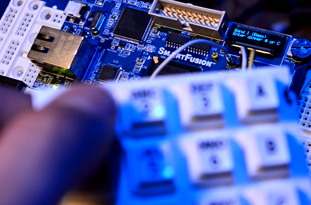
OLED Display
The OLED display on the SmartFusion eval board was used as a character display to show the menu system for the programming UI.
The display interfaces with the SmartFusion using the I2C bus.
LED Control
We implemented a simple memory-mapped I/O peripheral in Verilog to control the LEDs on the SmartFusion eval board. The LEDs display the status of the lighting control outputs even if the DMX output is unconnected.
SmartFusion Microprocessor Subsystem
The SmartFusion MSS is a set of cores that integrate tightly with the ARM core and FPGA on the chip. The MSS provides an integrated bus interface, external memory controller, peripheral controllers, interrupt and clock management, DMA controller, and other pieces useful during system integration.
Microsemi also provides ready-to-use firmware and device drivers for the hardware components in the MSS.
We used a lot of MSS logic in this project.
Analog Subsystem
The SmartFusion's ADC and other analog hardware is configured through the MSS. We configured the ADC to sample at 25 KHz and provide buffers of 1024 samples at once to the processor via DMA.
I2C Controller
We used an I2C master on the SmartFusion's MSS which is hard-wired on the eval board to the OLED display.
Microsemi provides a driver for using the OLED display via I2C.
SPI Controller
We used an SPI master on the SmartFusion's MSS, which is hard-wired on the eval board to the 8 MByte SPI flash. We used the SPI flash to store the user's configuration settings.
A reference document from Microsemi provides a simple driver for using the flash memory via SPI.
UART to USB Interface
A UART controller on the SmartFusion's MSS is hard-wired to a UART/RS232 - USB bridge. We used this interface to dump debugging output which can be read using HyperTerminal or PuTTY.
Component-Level Project Diagram
Software
The majority of our software is DSP code, which is described in detail below. Most of the other code is for the programming UI, and the remaining code is mostly hardware initialization and control code.
Menu/Programming UI
We use a simple numeric keypad (with a few additional alpha keys, A-D) for the programming UI. The keypad is sourced from uController.com and has a simple UART interface.
The menu system is implemented in C as a simple state machine.
As soon as the user makes a change to the system's configuration via the menu, the new configuration is written to the SPI flash memory.
Hardware & Drivers
We used a driver to interface with every piece of hardware in the system. Hardware that was part of the SmartFusion MSS (like the UART, I2C and SPI controllers) included drivers from Microsemi.
We developed custom drivers for all custom hardware, like the DMX cores and the keypad.
The drivers we wrote for the DMX cores were released as open-source software.
Software Implementation Overview
The core of our software is implemented in an infinite while loop at the end of the main() function.
Two interrupt service routines (ADC samples received from DMA and character reveiced from keypad) set
flags and other status variables to trigger actions (menu state machine transitions and DSP code) in the while loop.
If the software were any more complicated, we would likely need to move to a simple RTOS. We're already using 100% of our CPU time, mainly on DSP, and providing good response time for menu keypresses was challenging. Any additional complexity would require a better system to manage CPU time.
DSP
Our DSP algorithm is fairly simple (though expensive in computing time). We take a buffer of 1024 samples from the ADC and run an FFT on the buffer. We take the magnitude of each of the resulting 512 samples and log-scale it. We calculate the mean magnitude and keep a running average of the last 20 mean magnitudes. Finally, for each frequency band, we find the peak magnitude and subtract the running average from that peak. The resulting 3 "normalized magnitudes", in dB, are then scaled to the range of acceptable DMX values (0-255).
A 1024-sample buffer, sampling at 25 MHz, means the system can respond to frequencies from roughly 24 Hz to 12.5 KHz.
Since we are only dividing the music into 3 frequency bands, we could build an algorithm using several FIR filters, which would require significantly less CPU time than the FFT. However, we had originally planned to divide the audio into 5 or 10 bands, which would make an FIR-filter-based solution impractical. We made the decision to use only 3 frequency bands late in the design process, and we chose to maintain the FFT-based algorithm so we didn't have to redesign and test the entire algorithm.
To ensure that this algorithm would work as hoped, we modeled the algorithm in Matlab before beginning our implementation in C on the target platform.
Rather than implementing the FFT and other DSP functions ourselves, we found a software library from ARM that provides a full library of DSP functions optimized for the Cortex architecture. Since the Cortex-M3 doesn't support floating-point in hardware, we used fixed-point math for most of our DSP, moving to floating-point (supported in software by the ARM DSP library) only for a small part of the algorithm.
Our DMX output logic gradually fades its output when lowering the intensity value of a DMX channel. This is important when controlling lighting instruments such as LEDs that respond effectively instantly to changes in input. (Standard incandescent lights have a response time on the order of hundreds of milliseconds.) During testing, we found that our controller created an unpleasant flashing effect with LED fixtures and certain music. We adjusted the DSP algorithm so that it can make lights brighter instantly but provides a pleasant fade when decreasing brightness.
Analog Hardware
Our analog hardware conditions the audio signal for the ADC input. There are four phases:
- Capacitors filter any DC bias from the input
- Stereo audio signal is summed to mono (and buffered through an op-amp)
- Antialiasing filter: 6th-order low-pass filter, corner frequency 10 KHz. We're sampling the audio at 25 KHz. The filter is composed of three Sallen-Key low-pass filters.
- Another op-amp sets a DC bias to keep the voltage level in the ADC's input range.
Results & Media
The system works! In the following videos:
- The blue component of the background light is assigned to bass (except for a red stripe on the right side which is also assigned to bass)
- The red component of the background light is assigned to midrange
- The green component of the background light is assigned to treble
- The red and blue lights on the left and right of the screen are assigned to midrange
- The white (uncolored) lights on the left and right of the screen are assigned to treble
- The brightness of the oval on the left of the background is assigned to midrange. The color of this light is controlled randomly by an upstream lighting control board.
- The brightness of the oval on the right of the background is assigned to midrange. The color of this light is controlled randomly by an upstream lighting control board.
- The brightness of the oval on the center of the background is assigned to treble. The color of this light is controlled randomly by an upstream lighting control board.
- The brightness of the light on the front of the model head is controlled by midrange. The color of this light is controlled randomly by an upstream lighting control board. Occasionally, the brightness of this light was also controlled from the upstream lighting control board.
- The white light which occasionally appears on the model head is entirely controlled by an upstream lighting control board.
This configuration demonstrates the audio-controlled lights and the pass-through capability which lets this controller supplement an upstream lighting control board. Note that in a "real" setup, the upstream controller would be responsible for controlling more lights, and our music-visualizing controller would control fewer lights. This setup would look less chaotic than this demonstration.
Music: It Could Be by Ella Riot
Music: Closer To The Edge by 30 Seconds To Mars
Music: Hello Seattle by Owl City
Music: White Knuckles by OK Go
The following video demonstrates the programming UI and keypad. In this video, the user adds a few DMX addresses to the bass band, removes one, then attempts to add an invalid DMX address (666).
You can also see several videos we created, mainly using Matlab, when developing and verifying the DSP algorithm:
- Realtime FFT of Replaceable by Ella Riot
- Realtime FFT of Robot Rock by Daft Punk
- Realtime FFT of Brain Damage by Pink Floyd
Conclusions
Our project worked as we intended, and we were lucky to be able to demonstrate it in a well-equipped light lab.
Given more time, our primary concern would be adjusting the analog circuitry, ADC settings, and DSP algorithm to improve the system's response. The current version of the system just doesn't respond well to low magnitudes in the input audio signal.
A secondary potential improvement would be improving the responsiveness of the menu system and programming UI. This would require having some way to interrupt the DSP code for key presses while performing writes to the I2C and SPI buses outside an ISR. This would get complicated, and the best solution would likely involve an RTOS.
Throughout the project, our goal was to create a final product as close to market-ready as possible, given our time and budget constraints. We achieved this goal. Very few tweaks would be necessary to turn this into a marketable finished product:
- Nice packaging + custom PCB
- Minor ADC sensitivity and DSP improvements
- Possibly a larger display for programming
- Improve performance of the programming UI
References & Resources
- The initial project proposal
- Actel/Microsemi MSS User Guide
- Actel/Microsemi Analog User GUide
- Actel A2F Eval Kit user guide
- App Note on using the SPI flash on the eval board
- MAX1480/1490 isolated RS485 interfaces
- CoreUART Handbook
- TI Application Note on active analog filter design
- ARM and Thumb-2 instruction set reference card
- ARM Cortex-M3 embedded software development app note (AN-179)
- EECS373 Project Handout
- EECS373 Custom expansion board docs
- Using Isloated RS-485 in DMX512 Lighting Applications
- Additional reference material from the EECS373 page
- Notes on summing stereo audio to mono
Released Code
- We released our APB3-CSR bridge as open-source hardware. Its Verilog source and documentation are available on Github.
- The C driver for the DMX cores was released as open-source software. The C source is available on Github.
Contact & Feedback
If anything in this document is unclear, you need additional documentation or information, or you find any errors - typographical or techincal - please contact Chris at chris@chrisdzombak.net.