Building the atomic clock I’ve always wanted
For years & years, I have wanted to own an actual atomic clock. So I built one.
Part of the Project Logs series.
For years & years, I have wanted to own an actual atomic clock. There’s no practical reason for this; I am, after all, currently wearing a GPS-enabled wristwatch. I just thought it would be pretty neat to have a household atomic clock.
Around half a decade ago, roughly in the 2014-2016 era, I began periodically searching eBay for “atomic clock” and related terms. This led, in 2016, to the $120 purchase of a used Symmetricom rubidium oscillator. It outputs an electronic pulse exactly once per second, so building a clock around it using an Arduino should, theoretically, be easy.
It wasn’t that easy.
Some troublesome details led to me overcomplicating and then abandoning the project in 2016:
I’d need to set the time on the clock, meaning I’d have to build some sort of user interface. This being my first embedded development project in 5 years or so, I wasn’t eager to hack together a bunch of buttons and end up with something harder to program than a VCR. Plus, it would be difficult to get the clock set perfectly accurately that way. I decided instead I could connect the Arduino to a computer over a serial port, and some software on the computer would set the time on the atomic clock over the serial interface.
Then, I decided the clock needed an integrated battery backup, since I did not want to have to connect the clock to my computer every time I had to unplug it from the wall. This further complicated the design — and made it heavier; this particular rubidium oscillator requires around 18 watts of power at startup, and consumes around 8 watts in normal operation, so I’d need a relatively large battery.
Finally, what sort of enclosure would I physically put this clock in? My woodworking skills precluded building a pretty wooden enclosure, and I knew hacking holes into a random plastic box wouldn’t make for a nice display piece.
I got so far as powering the oscillator up and verifying it worked — more difficult than it sounds, for reasons I’ll discuss below — and then the oscillator, Arduino, and other parts I’d accumulated sat in a box for 5 years.
Using the SA.22c Rubidium Oscillator
I’ll get back to the story in a moment, but first I wanted to review the oddities and difficulties that made using this oscillator a challenge. (I’ll also note that, with a larger budget, I could have chosen any of several newer oscillators that alleviate a lot of these pain points.)
You can follow along and learn more, if you’d like, by referring to the [SA.22c’s datasheet](/files/sa22c/SA22c Datasheet.pdf) and [user guide](https://dist.cdzombak.net/files/sa22c/SA22c User Guide.pdf) (PDFs).
Power
The oscillator requires both a 15 volt and 5 volt supply. It draws up to 1.2 amps at 15 volts, and only up to 100 mA at 5 volts.
This is unusual for an Arduino project, which led to the question: how will I supply that, while also supplying the 7~12 volts required by the the Arduino Mega (the Arduino I had chosen for this project)?
The solution, helpfully suggested by my dad, was a “buck-boost switching regulator” — in this case, a MAX16930. I got an evaluation board for this regulator, and modified it to provide the necessary 15V, 8V, and 5V outputs from a 12V input.
I don’t remember exactly what I did to that board — this was over 5 years ago — but [here are my notes from that project](https://dist.cdzombak.net/files/atomclock/Power Supply Notes.pdf) (PDF).
2mm-pitch Connector
The oscillator’s connector is an oddball one, with a 2mm pitch instead of the much more common 2.54mm pitch standard on everything in the Arduino and Raspberry Pi world. It was difficult even to find a large-enough protoboard with a 2mm pitch, and of course I wouldn’t be able to mount any 2.54mm-pitch components to the board.
Once I did, I noticed that the connector on the oscillator was significantly inset, so the mating connector had to be mounted maybe 2mm off the protoboard, rather than flush. That, of course, complicated soldering wires to the connector on the opposite side of the protoboard. Getting good connections here was an issue several times during this project.
Heat
This wasn’t as much of a pain as the oscillator’s power requirements and odd connector, but it still bears mentioning. The oscillator literally contains a heater, and it needs to be warm but not too hot to operate. Its user guide recommends attaching a heat sink.
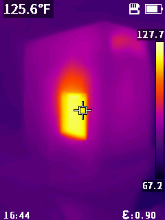
So, my enclosure design includes an opening for a heat sink, and it does indeed get hot: it seems to stabilize at around 125ºF.
2021 Design Discussion
Recently I’ve been playing with Arduino on the ESP8266 platform, and it occurred to me that this could solve all my problems around setting the clock: once the oscillator is ready, I can simply have the microcontroller connect to WiFi, sync the current time via NTP, and then disconnect from the network, relying on the rubidium oscillator’s 1 pulse per second (1PPS) output to keep time. Since the clock will now have calendar information, this also allows the microcontroller to display the current date, local time, and UTC time — and even account for daylight saving time!
This updated concept is much simpler. I don’t need any user interface for setting the time, and I don’t have to worry about a battery backup, since the clock will just fetch the current time via NTP whenever it boots.
The design, at a block-diagram level, is straightforward. It’s essentially just the power supply, the oscillator, the ESP8266, and the display. There is, however, the new complication that the ESP8266 requires a 3.3 volt supply and 3.3 volt logic levels. So, I added a 3.3V regulator and a level shifter, allowing the ESP8266 to interface with the oscillator’s 5V logic levels.
I started working from this rough-but-functional block diagram:
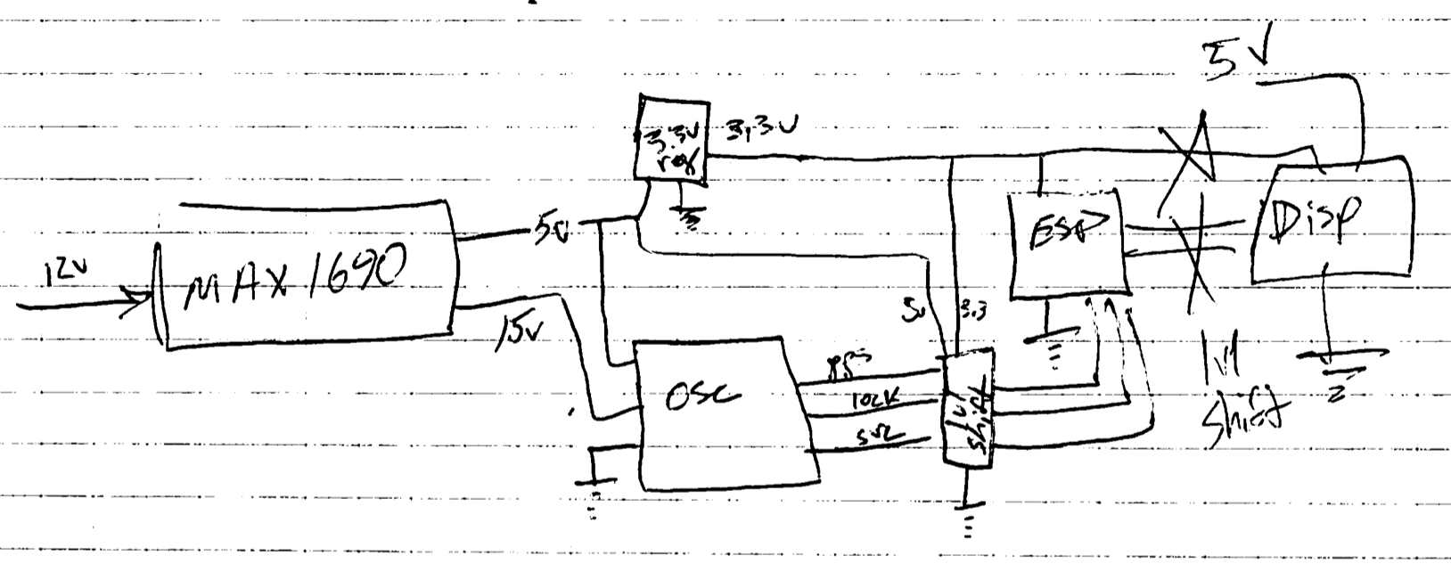
You’ll notice some confusion on the right-hand side of the diagram. I’d initially assumed that the display I chose — this easy-to-use RGB character display from Adafruit — would work with 3.3 volts, but it requires 5 volts. (Always check your assumptions! I thankfully found this error before I actually began wiring this part of the circuit.)
This created another issue, though. The level shifter I’d obtained (a cheap one from eBay intended for I2C buses) could only handle 4 signals, and now I needed 5:
- 1PPS signal from the oscillator
- Ready indicator from the oscillator[1]
- Service indicator from the oscillator[2]
- I2C SDA between the ESP8266 and display
- I2C SCL between the ESP8266 and display
I figured I'd use the level shifter for everything except the oscillator's service signal, and given the parts I had on hand at home, I used a simple voltage divider to convert the service signal from 5V to 3.3V. (Thankfully, all the oscillator → microcontroller communication is one-way.)
This didn't quite work out. The 5V 1PPS signal from the oscillator is a very short pulse; it lasts 400 nanoseconds:
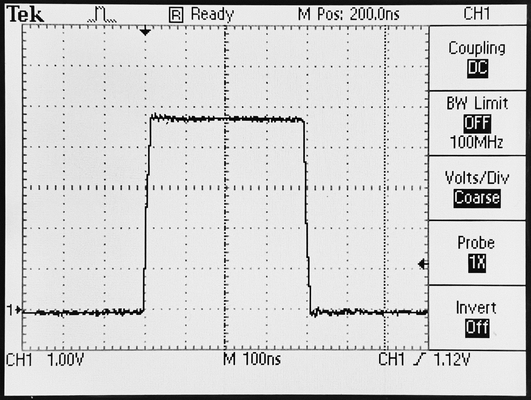
The level shifter was not intended for this type of usage. After passing through the level shifter, these pulses barely reached above 1.5V — hardly the 3.3V they should have. They simply don’t last long enough for the level shifter’s output to reach a logical high.
Instead, I moved the oscillator's service signal to the level shifter, and I used the voltage divider (500 ohms / 1000 ohms) on the 1PPS signal. The result still isn’t pretty, but it reaches 3 volts and gets the job done:
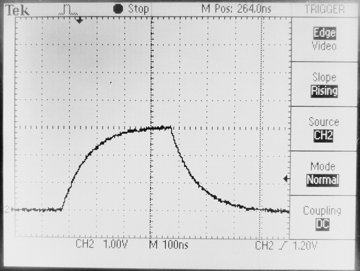
The ESP8266 won’t trigger an interrupt on the rising edge of this signal, but I found it seemt to trigger reliably on the falling edge. And the oscillator’s ready and service signals make it through the level shifter just fine, as do the I2C signals between the microcontroller and the display.
Update, December 14, 2021: I've begun to suspect this voltage divider's performance is inadequate, and I plan to replace it by a 74LVC245. I would've liked to do this when first assembling the project, but — as noted above — this solution was dictated by the parts I happened to have on hand at home, which didn't include any inverters, Schmitt trigger buffers, or the like.
While I'm at it, I'll also move the other oscillator signals (ready/lock and service) to this new shifter, rather than running them through the I2C shifter.
In the software discussion, you'll notice that that any timing variation introduced by the voltage divider won't affect the clock's accuracy over time; if a pulse arrives at the microcontroller with a variable but small delay, the time is still incremented by 1000ms. But a *missed* pulse would cause the clock to lose a second — an error that would accumulate over time. I think this is possible with this voltage divider; given that the ESP8266 wasn't able to reliably trigger an interrupt on the rising edge of that waveform, I suspect that it may not be triggering one perfectly reliably on the falling edge.
A future post will discuss this change in detail.
The other major change from 2016 is that I now have a 3D printer. This allowed me to solve two problems:
- What enclosure will I put the clock in?
- How do I keep the various electronic boards & parts together while I’m assembling them?
Assembling the Electronics
I started by designing and 3D-printing a carrier assembly which would keep the oscillator board, power supply board, and other electronics safely together. This alleviated a problem I ran into in 2016 — an ad-hoc assembly of several boards sitting on a desk is fragile.
Armed with the carrier assembly, a completed block diagram, and carefully-considered pin assignments, I began putting everything together.
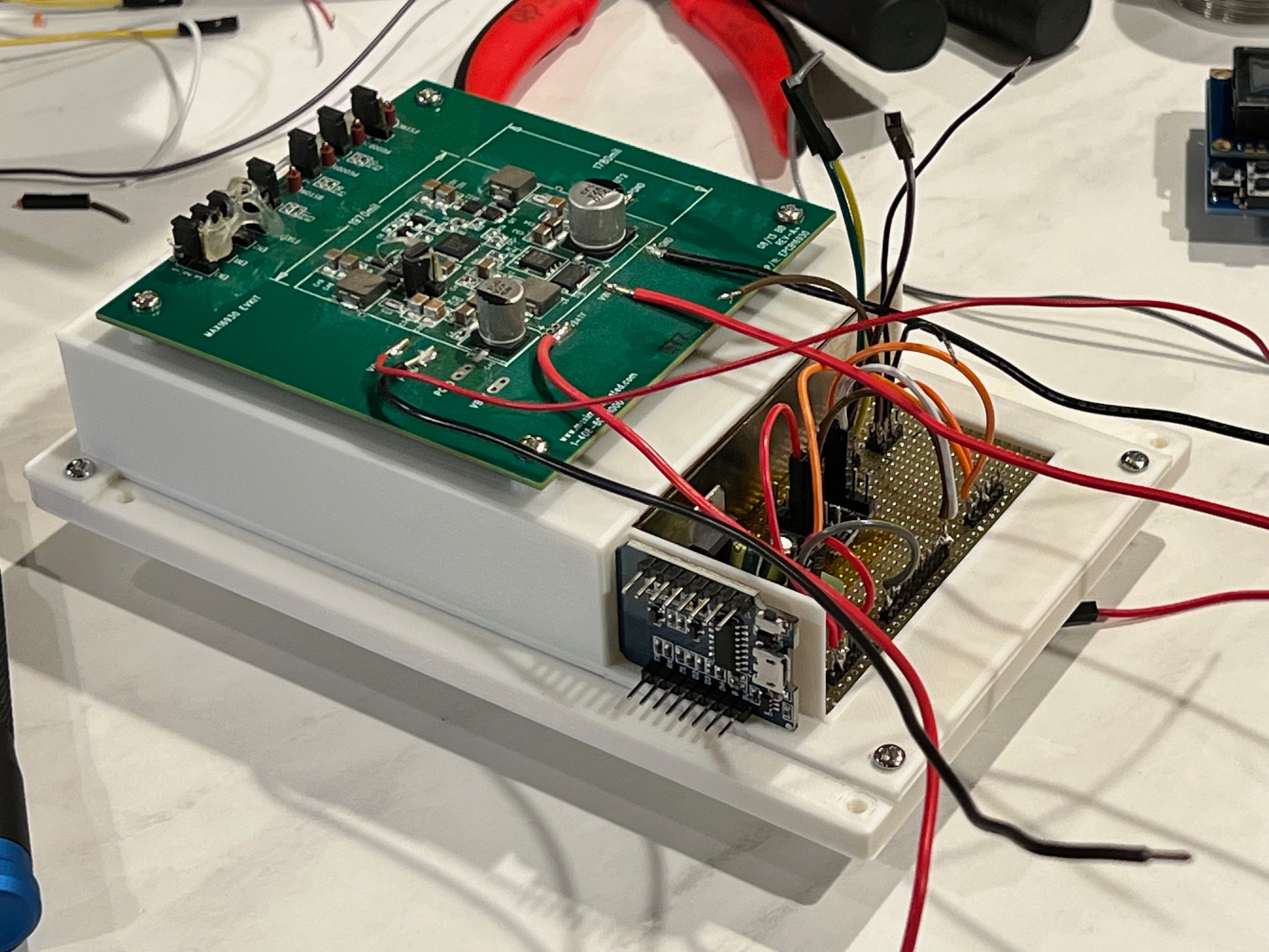
At this point, I had the oscillator (the silver rectangle hiding inside the white plastic assembly) powered up, and I verified it still worked:
Later, with all electronics connected and working, the project looked like this:
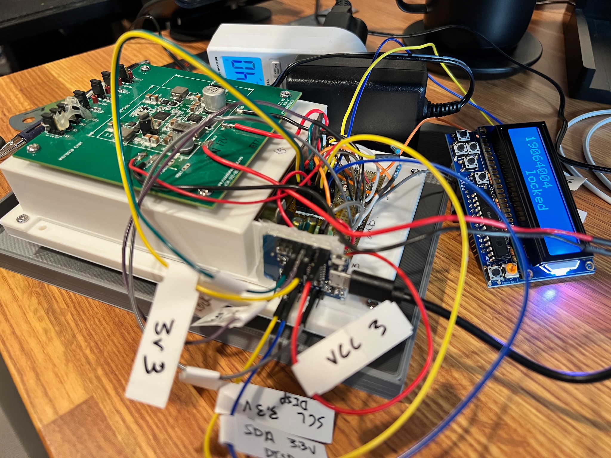
Definitely messy, but at least everything was held together securely.
If I were starting totally from scratch, I’d likely try to design a custom PCB for this. That would let me consolidate the multiple protoboards, the level shifter board, and the ESP8266 board into one unit despite the oscillator’s oddball 2mm-pitch connector. However, since I had already successfully mounted the oscillator to a protoboard, I decided I’d just wire everything together and hot-glue the various smaller boards in place.
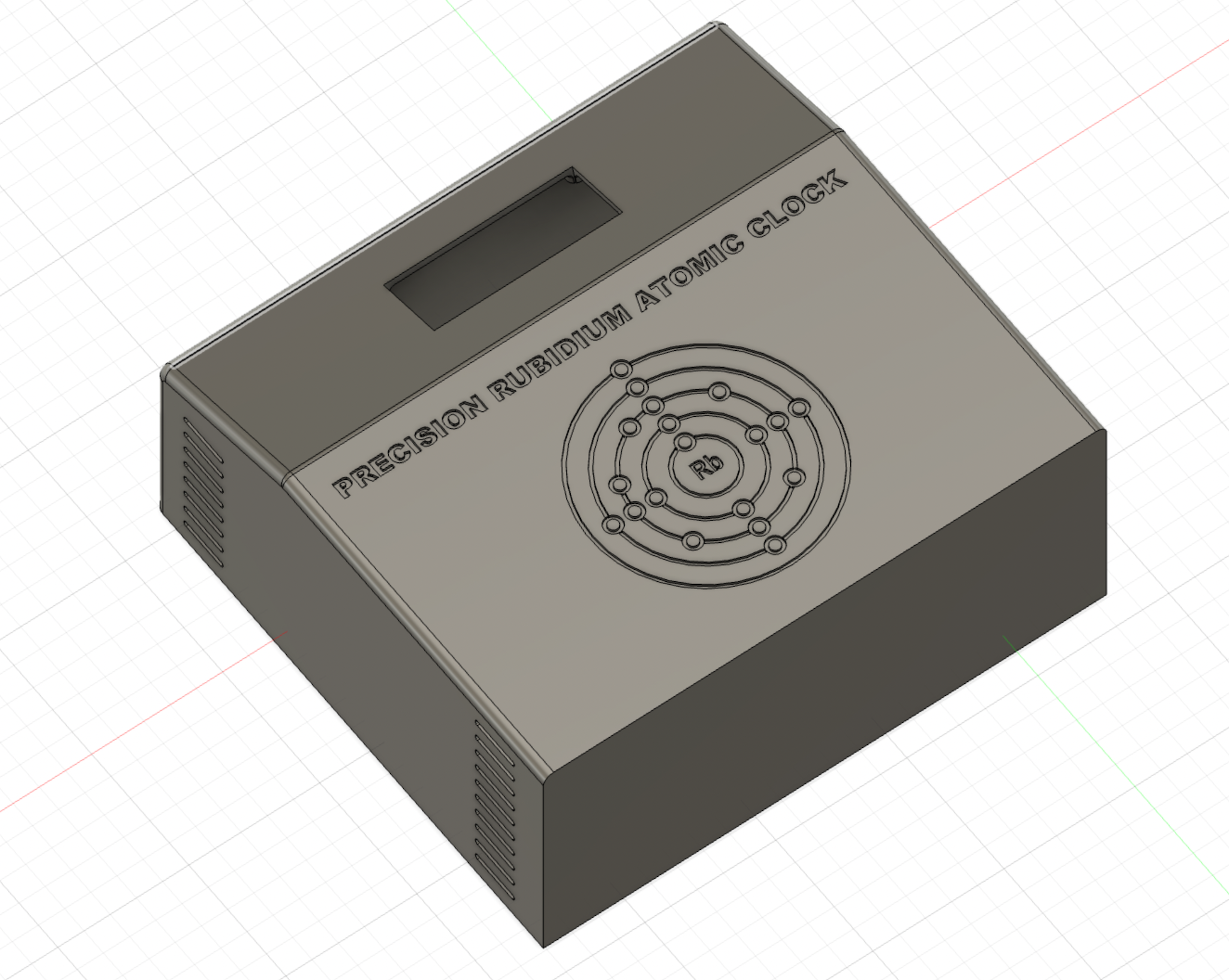
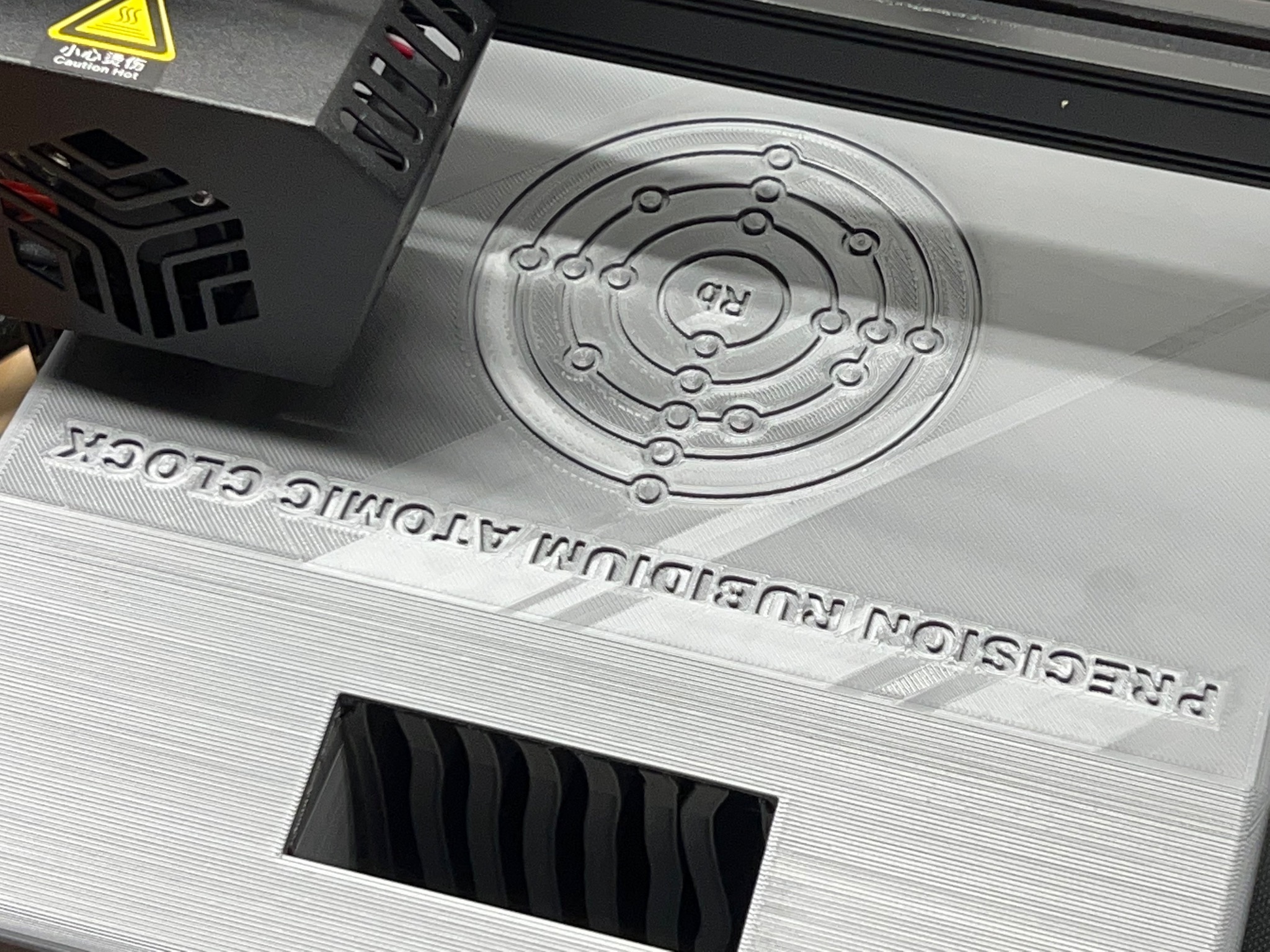
Enclosure Design & Production
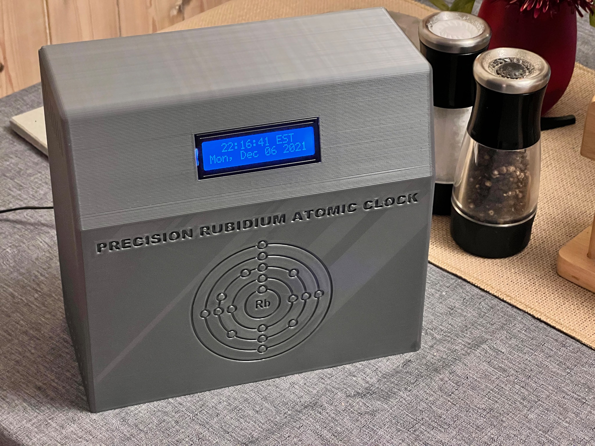
I designed a vaguely retro-tech-style enclosure in Fusion 360, complete with an electron shell diagram of the rubidium atom[3]:
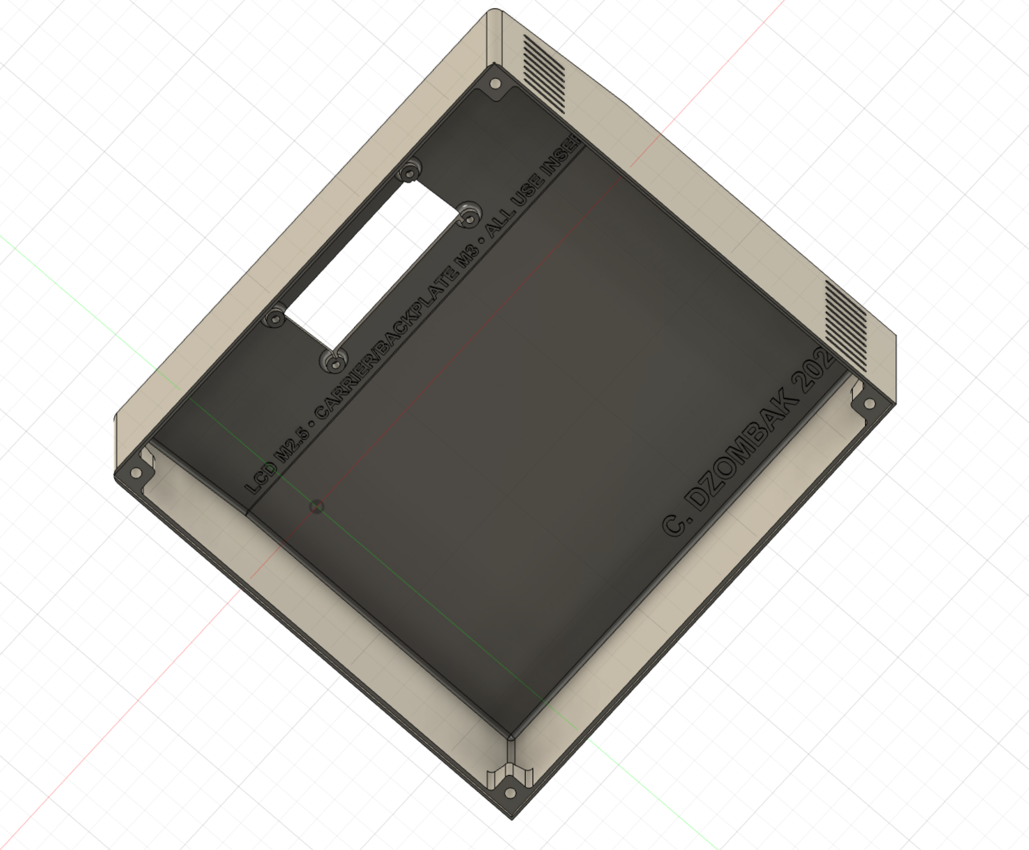
The electronics carrier assembly simply screws onto a backplate, which is then screwed to the back of the clock enclosure. The screen is screwed into specifically-designed mounts on the inside of the case, allowing the front of the clock to remain clean with no exposed fasteners.
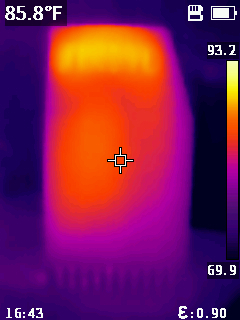
The side of the enclosure closest to the oscillator has some ventilation along the top & bottom. You can see this ventilation working in a thermal camera photo:
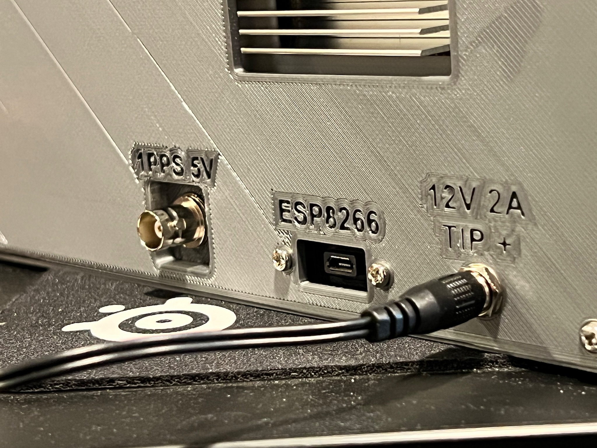
The backplate includes three connectors: power, a USB port for programming the ESP8266, and a BNC jack connected to the rubidium oscillator’s 1PPS output:
It took me three tries (and I wasted at least 1kg of filament) to print this enclosure successfully. As it turned out, the shallow angle of the front meant the enclosure requires support during printing, and I didn’t want to have supports attached to the front of the enclosure, since that would affect surface quality. Then, 80% of the way through my second printing attempt, at around 2am, the filament snapped, and I was unsuccessful in resuming the print. But, after a solid week, I had successfully printed the enclosure and backplate.
Software
The software is possibly the least interesting part of this build. It’s on GitHub, in my atomclock repository. As with my previous ESP8266 work, it’s built using PlatformIO and Arduino.
The system uses a simple state machine:
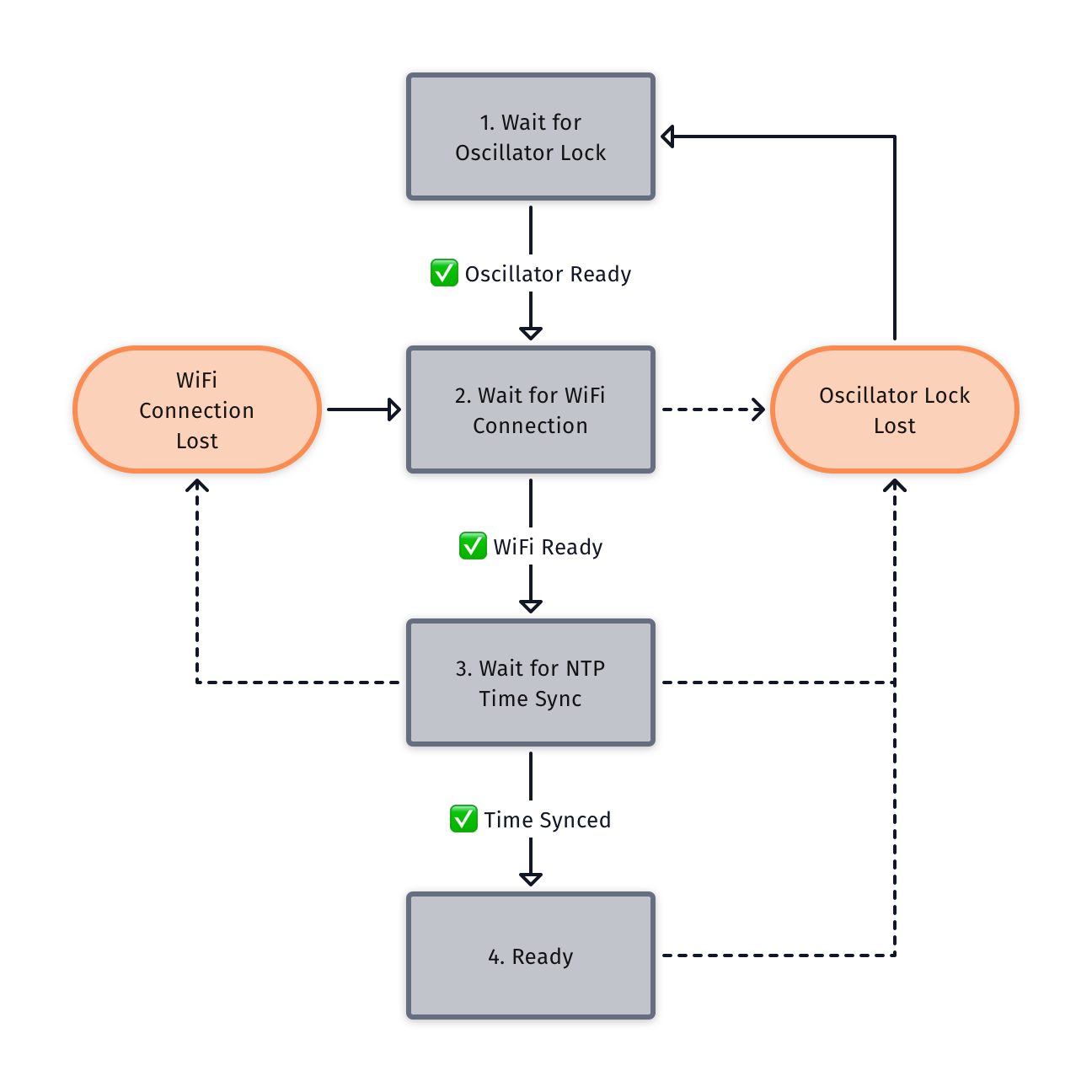
- On start, the system waits for the oscillator’s ready (“lock”) signal
- Then it initializes and waits for a WiFi connection
- Then it begins and waits for an NTP time sync
- Finally, WiFi is disconnected and the clock is ready for regular timekeeping operation
The timekeeping logic is simple. I arrived at this solution after carefully reading the ESP8266 Arduino core’s time.cpp code, which internally does almost exactly what I want to do: track an offset between the system’s micros() time counter and the current time.
By default, this offset is set by NTP and then not adjusted again. However, after the oscillator is ready, my clock’s code:
- Syncs the current time via NTP
- At the next 1PPS pulse from the oscillator, reads the current time (including microseconds!) from the Arduino core into a variable
- On every subsequent 1PPS pulse, increments that variable by 1 second and sets the core’s time
This results in the Arduino core adjusting its offset between the micros() time counter and the current time every second, keeping it in sync with the rubidium oscillator while using the ESP8266 board’s clock to measure sub-second intervals. This means all calls to time() from anywhere in the application will return the correct, current wall clock time. And, importantly, I avoid the problem with a naive pulse-counting implementation (if I just counted 1-second pulses, and used that to tell time, that pulse counter could be off from the actual time by a significant fraction of a second).
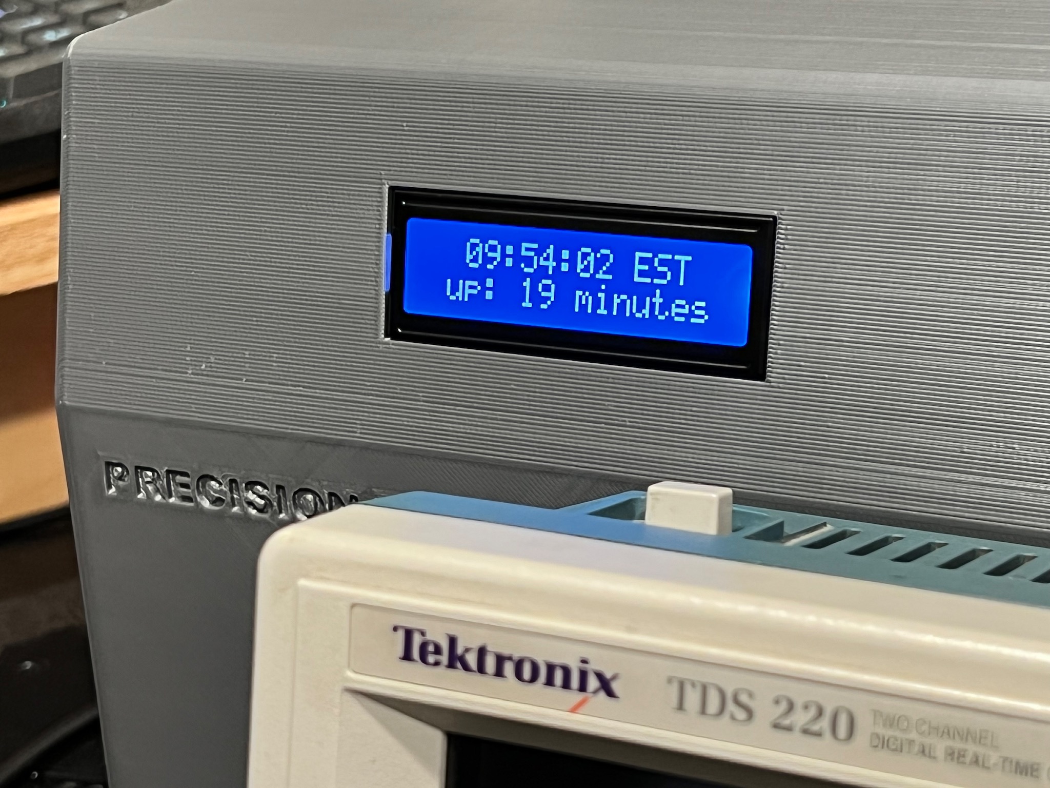
In addition to displaying the date, for the first few seconds of the minute, the display’s second line reports the clock’s uptime:
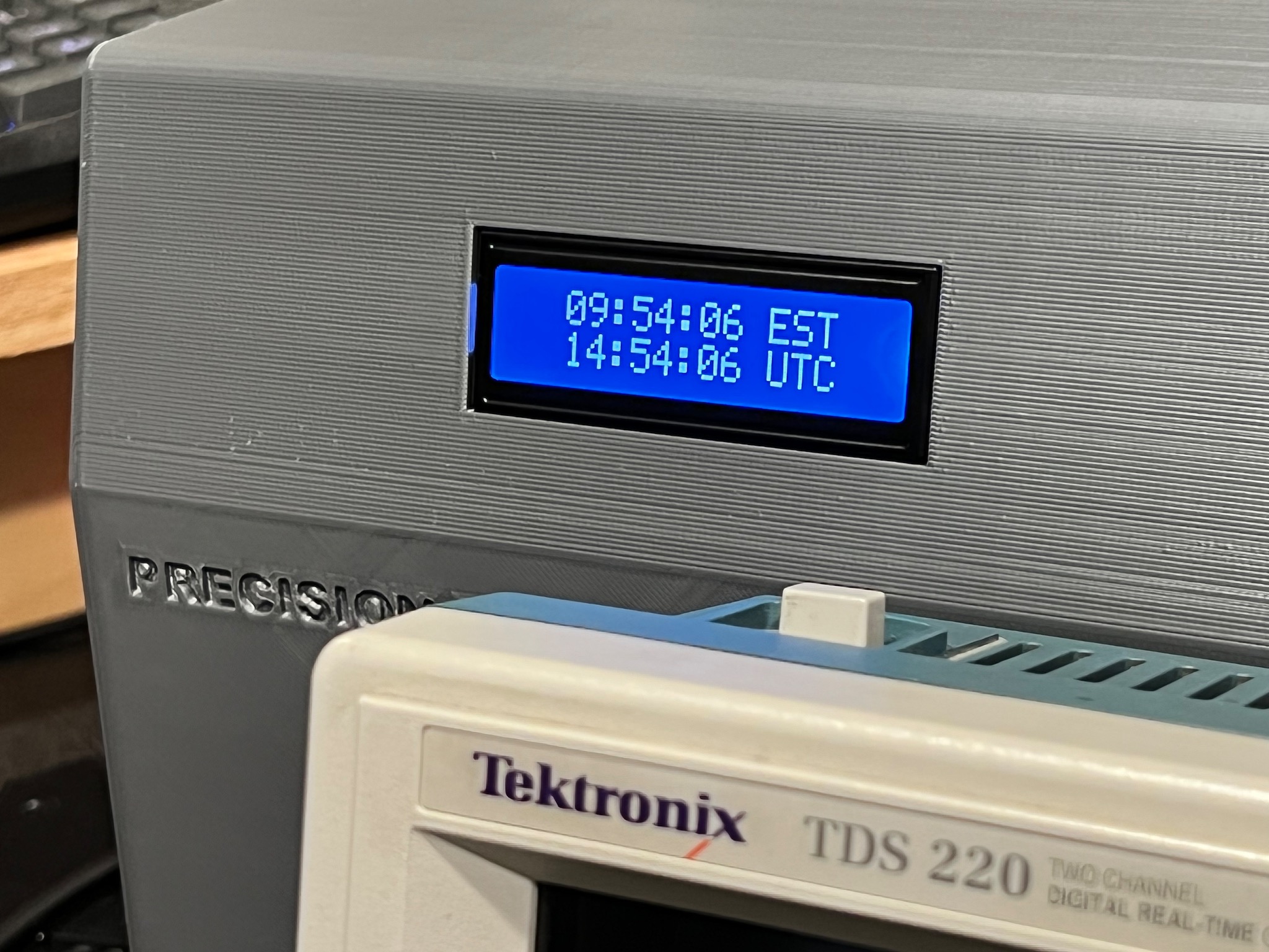
And then, for the next 15 seconds, it displays the time in UTC, before returning to displaying the date:
Results
I’m very happy with the result. It’s shown here on the kitchen table, but its permanent home is a shelf next to my desk:
As I noted at the start of this post, I didn't build this for practical reasons: it’s a clock that consumes 8 watts and is every bit as accurate as the time displayed on my iPhone.
But I’ve always wanted my own atomic clock, and now I finally have one!
This "ready" signal is actually called "lock;" in this post I try to call it "ready" for clarity, but you'll see it called "lock" in some of my handwritten notes & elsewhere. ↩︎
This signal will indicate when the oscillator requires service from the manufacturer. The SA.22c oscillator is discontinued, so I assume either I won’t be able to get service, or it would cost some absurd amount of money. When this time comes, I’ll probably just try to buy another used one somewhere. ↩︎
This diagram originally came from Wikimedia, and I spent a truly ridiculous amount of time in Fusion 360 to get it to turn out well. ↩︎