Socket organizers, end caps, and 3D-printed friction fits
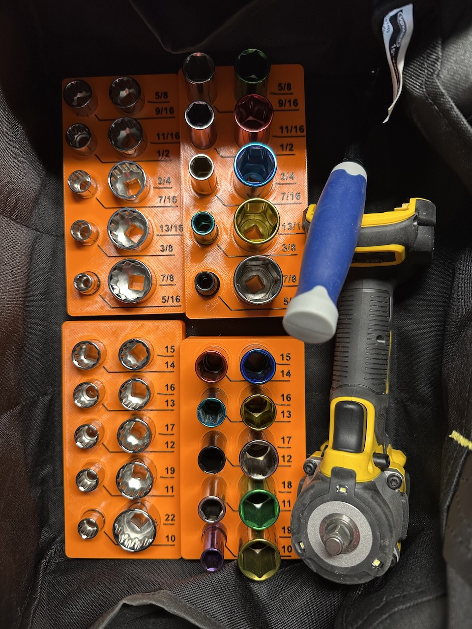
Another recent 3D printing project was customizing these socket organizers for 4 socket sets that live in a tool bag with my 3/8" impact wrench:
Since these live in a tool bag instead of in a drawer, I wanted to be sure the sockets would fit snugly in the organizer but/and be easily removable by hand when needed. So I had the same problem as with the end caps for my table saw's aluminum extrusions: getting a Goldilocks-level just right friction fit.
I decided to print both these projects in 95A TPU, since I figured the softer and semi-flexible objects that result will stand up better to the stresses of frequent use and would make a good friction fit easier to achieve.
But how do you reliably get good friction fits when desigining such parts? A lot of factors need consideration, and I have a few rules of thumb, but — spoiler alert — ultimately it comes down to trial and error.
Considerations
Offset
How far should your 3D-printed design be offset from the target object's profile in CAD? Unfortunately I have no hard-and-fast rule to offer. It depends, heavily, on everything listed here and probably on some other factors I've forgotten.
Depending on the size of the objects involved and how accurately I've measured them, I use something between 0.05mm and 0.2mm as a starting point.
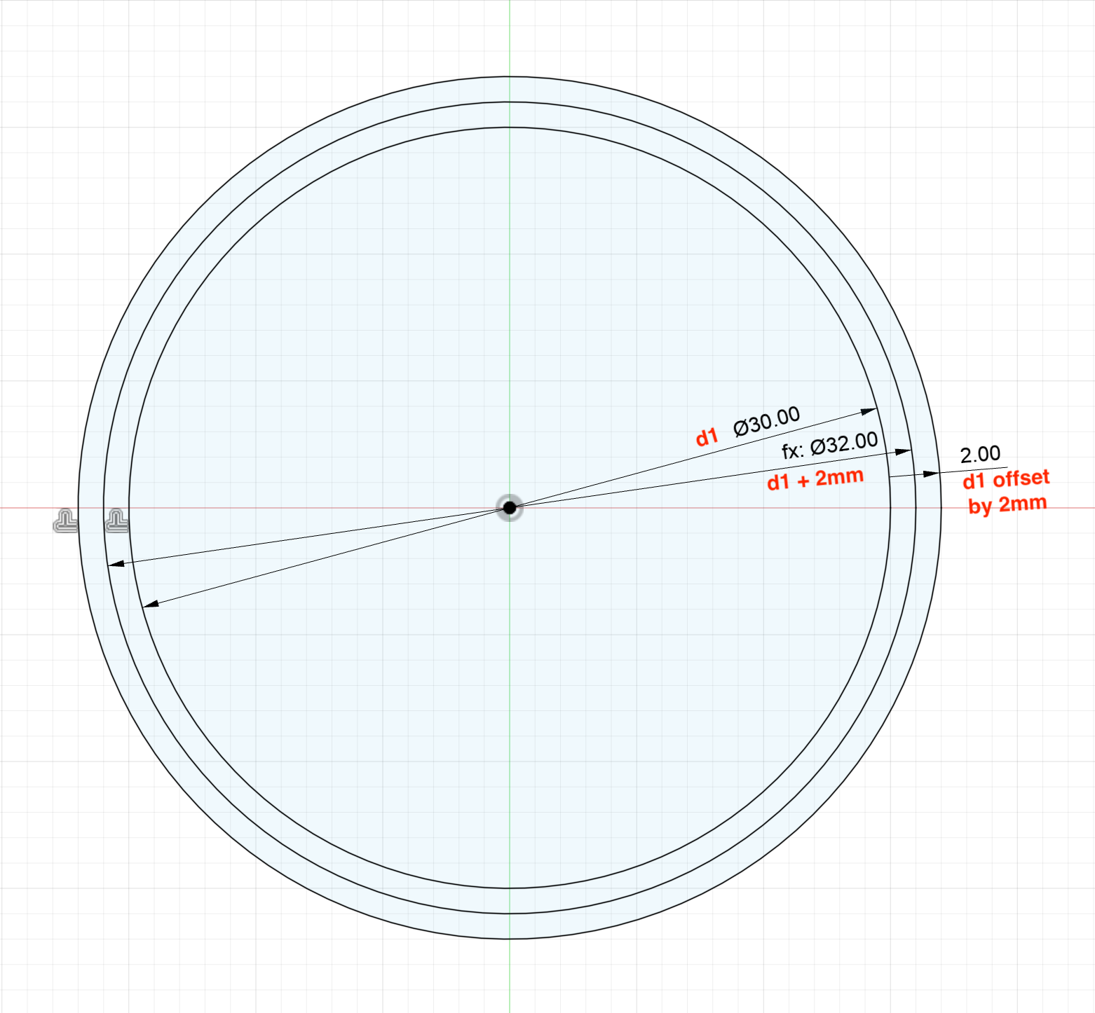
Note: diameter vs. offset in your CAD tool
Remember that specifying an offset of, say, 0.1mm from a circle's edge is not the same as increasing the diameter of a circle by 0.1mm. Increasing a circle's diameter by 0.1mm only results in a line offset by 0.05mm.
Interface surface area
The total surface area of the interface between two parts will have a large impact on how much friction there is and consequently how securely they fit together.
This also means that, for particularly small interface surface areas, your tolerances need to be much more accurate than for large surface areas. This is why, for those extrusion end caps, I added internal contact surfaces and made them taller than the visible ones: I wanted to increase the total interface surface area so I had a little more room for error in design/manufacturing.
I learned this the hard way on another recent project, about which I have yet to blog. I printed push-on friction fit lens caps for a few camera lenses in my collection. One of the lenses is tiny; its diameter is around 25mm. This meant its lens cap has a relatively tiny interface surface area, and it took me almost 10 iterations of sub-millimeter adjustments to get a good fit.
Another lens had a diameter around 51mm, and given the much larger interface surface area — and the resulting increase in allowable tolerances — it only took me a couple iterations to make a lens caps that fit perfectly fine.
Wall thickness
Particularly when using flexible filament, a wall printed with many loops (3 or more) will have less "give" than a wall printed with a single loop. You'll need to consider this when determining how much of an offset to use for your friction fit, and weigh it against the strength considerations that typically determine the choice of wall loop count.
(This also depends on nozzle diameter.)
Careful measurement
Accurate and careful measurement of the parts involved in a friction fit is critical. Again, with larger parts (and the resulting larger interface surface) it's less critical, but it's still critical.
For things like these socket set organizers and lens caps, I measured the relevant objects with a good set of calipers to within 0.05mm.
For larger and less critical objects, like the extrusion end caps, I found that modeling the extrusion's profile to within about .2mm of accuracy was good enough.
Printer dimensional accuracy
Dimensional accuracy is a challenge in 3D printing. Variables that influence include the quality of the printer, the amount of calibration that's been done (both by you and at the factory before its delivery), filament material, nozzle size, and print settings.
Ultimately you can deal with this by carefully calibrating everything for a given material/nozzle/print setting combination, adjust slicer settings to better compensate for this problem in a given print, and/or adjust diameters and offsets in your CAD software directly. You may also be able to minimize error in the dimension you care about by choosing an alternative orientation for your object on the print bed.
Material contraction/warping during printing
As printed plastic cools, it may contract and warp the print. Some choices that affect this are filament type, layer height, hotend temperature, bed temperature, chamber temperature, fan settings, volumetric flow rate, wall thickness, and infill type and density.
As with dimensional accuracy, remember that this contraction and warping will occur differently in the Z axis. You may be able to use that to your advantage.
Materials
What materials are in play? A friction fit between TPU parts can probably deal with looser tolerances than a friction fit between two hard plastics. A good fit between smooth aluminum and even a very soft TPU probably needs relatively tight tolerances.
Dust
Will there be dust between the surfaces in this friction fit? (For a table saw part, the answer is yes!) What size of dust? Will the dust increase or decrease friction between those surfaces?
Temperature & thermal expansion
How much of a temperature range will this friction fit be exposed to? And how much do the involved materials' coefficients of thermal expansion differ?
Trial and error
Despite my best efforts, with so many variables I usually find that some trial and error is needed. This iteration would ideally take place with the same materials, contact surface area, print settings, etc. that you plan to use in the final product.
At the same time, it's important to optimize this process to reduce the time required and material waste.
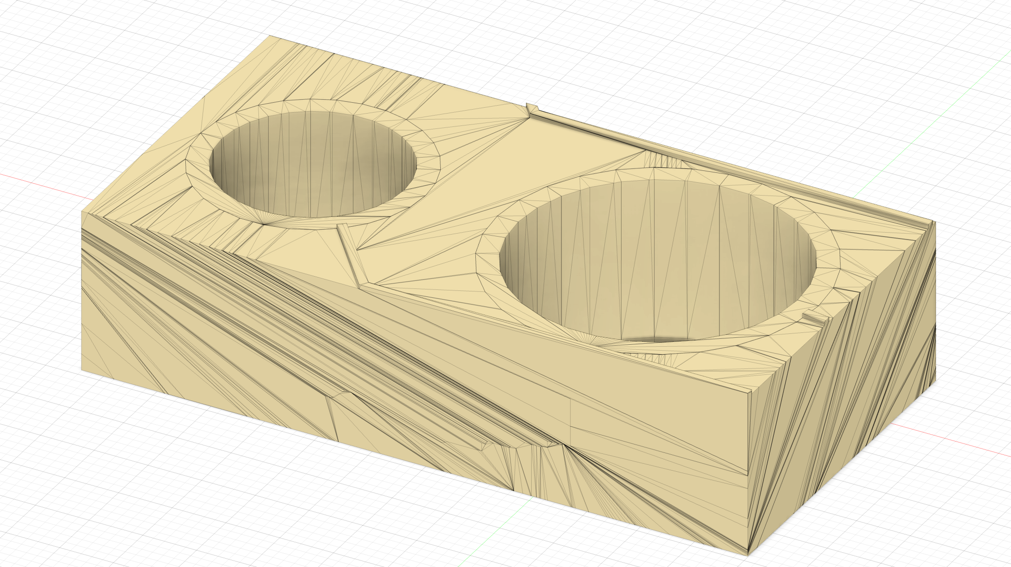
In the case of the socket organizers, I used Autodesk Fusion to chop out a small section of one organizer. My theory there was that if two sockets fit nicely, they all should, since I took the same careful measurements of each individual socket:
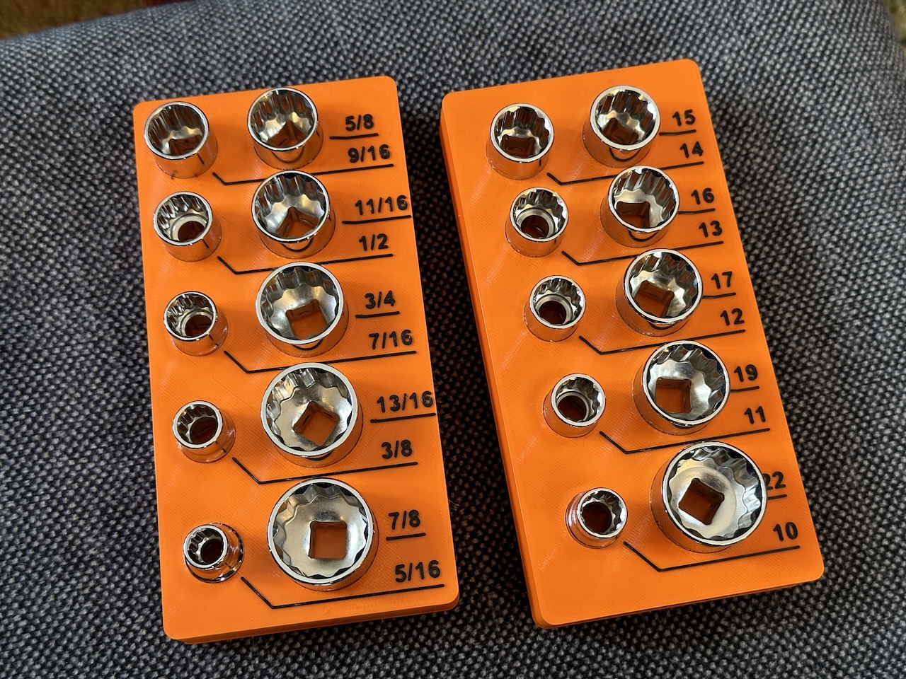
The resulting 3/8" socket organizers
With all that out of the way, here are the STLs and OpenSCAD source files for these 3/8" socket organizers. Specifically, these are designed for these socket sets from Harbor Freight:
- 3/8 in. Drive Metric Color-Coded Deep Socket Set, 10-Piece (SKU 69346)
- 3/8 in. Drive SAE Color-Coded Deep Socket Set, 10-Piece (SKU 69344)
- 3/8 in. Drive SAE & Metric Chrome Socket and Ratchet Set, 21-Piece (SKU 64536)
(This embedded 3D viewer is very much a work in progress; please forgive its flakiness!)
The resulting socket organizers at home in their tool bag: